C4DI Hardware Meetup - You Should Come Along - Really

If you live in the Hull area and have any kind of interest in technology there's a very good chance you'd enjoy a C4DI hardware meetup. They are first Thursday of every month and we have a mix of folks who like playing with computers and hardware and stuff. This month we had a Raspberry Pis of various flavours (which sounds wrong but it's right), flashing lights, amazing embedded devices you can get for less than a fiver and some brilliant discussions amongst other things.

Keep an eye on the Hull Meetup site for the next one.

Organising Components

While I was up town recently I noticed these rather stylish boxes in Tesco that you can get for a reasonable price. 

I'd been looking for some way of storing my increasing collection of electrical components. I have this worrying (but, fortunately not very expensive) habit of searching ebay for the word Arduino and then being completely unable to resist buying things I find at amazing prices, post free from China.

My plan was to fill each box with envelopes containing particular components.  I stole the idea from the excellent Arachnid Labs blog

It works really well. When I want something I just have to flick through the envelopes to find it. The Computer Scientist in me will probably sort the envelopes into alphabetic order at some point, but for now I've not got enough devices to really make it necessary.I don't have any anti-static envelopes, so I just used ordinary stationary ones. 

Hardware Group at C4DI

WP_20140116_18_30_40_Raw__highres.jpg

Tonight we had our first meeting of the new C4DI hardware group. There seem to be lots of peple who are keen on getting to grips with hardware and embedded systems, with interest in Raspberry Pi, Arduino and Gadgeteer to name a few. I took along some toys, as had other folks. Above you can see the insides of my Tagomatic device, along with some pinball machine related shenanigans which includes using an Arduino to capture messages inside the pinball table circuitry and some coils of electro-luminescent wire. That lights up and looks really cool. 

Stay tuned for details of future events, this looks like it is going to be great fun, and it's not too late to sign up over at the meetup page for C4DI.

Final Tags of Fun Lecture of 2013

image_thumb[2]

This is the latest design for the “Tagomatic” box. Expect a smaller one for next year.

We had our last 5:15 pm lecture today. I can’t say that I’ll miss them, although this one was quite fun. I went through the exam paper for last year (you can’t get more fun than that) and gave away four owls, including a “Golden Christmas Owl” to someone who’s name I completely failed to pronounce properly. Oh well, perhaps the next version of the “Tagomatic” can have text to speech. For those that haven’t heard of it, the “Tagomatic” is a little Gageteer powered box that reads the RFID tags of folks at a lecture and then picks a random winner from the assembled multitude. I first used it for the welcome party, where we had it allocating the free drinks, and I’ve been using it in my Friday First Year lectures to make things a little more interesting.

People have seemed to engage very well with the project, bringing along their tags and scanning them for a chance to win small prizes. I even had someone get in touch asking where they can get a tag from…. Next year I’m planning to have multiple tag readers, spot prizes and Bluetooth networking back to my phone.

It almost makes me wish for another 5:15 lecture on Friday. Almost……

John Mayer at the O2–thanks to Hacked

In July this year I took part in Hacked at the O2 in London. It was an absolutely brilliant hackathon, made all the better by the fact that I managed to win one of the competitions. My Difficultifier got People’s Choice Award, which was completely wonderful. What made it even better was finding out that part of the prize was four tickets to any show at the O2 Dome over the next year. Splendid.

I mentioned this to Number One daughter. “John Mayer’s playing the dome in October” she said. Done.

So, thanks to those wonderful O2 people, particularly Cristiano Betta and Kevin Prince, today we were sitting in seats up close to the stage, having just come from the O2 Lounge where we had been preparing for the performance with a couple of cocktails. As you do (or as had been laid on for us)

DSC03250.jpg

This is Gabrielle Aplin, who did a sterling job providing support and had an absolutely cracking backing band.

DSC03381.jpg

.. and this is the man himself, with some good advice for us all. He started early and gave us a two hour demonstration of why he is just so darned good. If you’ve not heard of John Mayer, then seek him out. Blues, rock, country, playing the guitar behind your back.  The works.  Just really, really good.

The Opposite of Planning

Untitled

“Plans are Useless. Planning is crucial”. I really like this statement. I reckon it boils down to the fact that even if you plan stuff carefully there is a very good chance that it will all go wrong. But it also says that if you don’t plan, things are even worse.

I reckoned I’d planned carefully enough. I had all the bits on hand to make the tags, I got the software mostly working on time. I was held up with a bug of mine that I blush to think about now, perhaps it will be the basis of a blog post in later days.

Anyhoo, the only thing missing was the little plastic envelopes that I’d ordered a couple of weeks ago to put the tag, and the name of the lucky owner, into. But they were bound to arrive in time, weren’t they?

No. So tonight we got to spend a chunk of time sticking bits of papers onto tags with bits of freezer labels that I’d “liberated” from the kitchen.  I know some of the labels will drop off, but it is the best I can do.

Number one wife gave me some sage advice. “Why didn’t I get some at the weekend, just in case?”. Indeed.

And I just know the little bags will arrive tomorrow.

“Tags of Fun”

Tag400

Regular readers of this blog (and yes there are some) may remember back in March when I made “The Door of Mystery”. This was an RFID tag powered raffle management system based on the .NET Gadgeteer. It worked very well when we used it for the Red Nose Day Lecture in Rhyme, and the people who bought tags to take part rather liked having them around, and hung on to them.

Which got me thinking. I’d like to be able to do prize draws and things in lectures, with bigger prizes if you’ve been along to more lectures. And I reckoned that these little tags might be a way to do this.

So I’ve invented “Tags of Fun”. We are going to give all the new students a tag each and I’m going to trial the devices at the Welcome Party on Thursday evening. We usually give “Drink Tokens” out, but this time everyone can use their tag with a customised “Door of Mystery” device to see if they can have a drink. The system will let you buy one drink, and then the head of department will have to use their magic “key of power” to reset the keys and allow more drinking.

Just to make things even more interesting, I’m going to link each tag with an owner, so the system knows the name of the tag holder.

Of course, now I have to get the software updated, download the student lists, build the user interface and program around 250 tags.

Before Thursday.

GHI Game–O

image

Sponsoring Kickstarter projects is kind of habit forming (OK, I’ve sponsored two other ones so far). Tonight I signed up for the GHI Electronics Game-O handheld console. This is not because I’m looking for a replacement for my trusty PlayStation Vita, but because I really fancy having a handheld console that I can program using C#.

The device is powered by the .NET Micro Framework and even contains some Gadgeteer ports so that it can be interfaced to all kinds of interesting hardware. I’ve a lot of respect for the makers, GHI Electronics, they’ve made some stunning little .NET Micro Framework and Gadgeteer boards and interfaces over the years (we use a lot of their hardware in our teaching) and I’m really looking forward to having a play with the device.

The project has reached it’s funding goal, but there is still time to get in there and get hold of one of these neat devices.

Building a Door of Mystery

IMG_6031_2_3.jpg

After a considerable amount of tweakage of designs and waiting for the printer to finish I now have my “Door of Mystery” machine complete. This is how it looks inside. I’ve added a WiFi card so that the door can upload pictures after they have been taken.

After all my careful planning the box needed a bit of surgery because I’d forgotten that power connector protrudes from the front of the board, but apart from that (and having to go and get some more bolts) it is now pretty much complete.

IMG_6067.jpg

This is the finished device. I’m going to have to slightly adjust the hole for the RFID reader in the next version, but it is quite pleasingly solid and works a treat.

You buy an RFID tag to enter the competition, show it to the “Door of Mystery” above and it will give you your entry number and take your picture. Then, I can use my special “Pick a Winner” tag to pick a random entry and even view their picture. We might even use this for bashes, where we might want to give out random prizes, pick team members or let people take it in turns to use some of the games.

Get a Scope

image

I really am a sucker for mailshots (hmm. Perhaps I shouldn’t put that in the blog). Anyhoo, I got a mailshot from Cool Components advertising the above (or actually the slightly cheaper version 2 which you don’t seem to be able to get any more). So I bought one. It is a tiny digital storage oscilloscope which costs around 80 quids or so. I reckon this is extremely good value. It has an SD card that you can use to store waveforms and the whole thing is powered by a Cortex A3 and open source, so you can even put your own firmware in there if you fancy it. It is powered from a rechargeable battery and will go up to 1 MHz which for me is fine.

If you are not sure what an oscilloscope is, it lets you “see” electrical signals. It draws a plot of the voltage in the signal as it changes over time. The original ones used a cathode ray tube that drew a single dot on the screen. The dot was moved across the screen at a regular rate by a timebase generator and the value of the voltage in the signal was used to control the height of the dot. If the signal was regular then you could take a a peek at the waveform and see what it was doing.  Newer ones are of course digital. The input voltage is converted into numbers which are then used to draw a graph on the screen.

Sometimes, when a circuit just doesn’t work you need to take a look at what is happening. A voltmeter will tell you if there is anything on the wire, but not how it is changing over time. If you have any hardware aspirations I think a little device like this is a pretty good investment, and it only costs around the same as a couple of video games.

Just the Wrong Size

IMG_6046.jpg

So today I had a go at printing out my designs. Above you can see the result. And I’d made a mistake that I’ve made before. I made the holes exactly the same size as the things intended to fit into them.

Do. Not. Do. This.

Of course they don’t fit. One thing just sits on top of the other looking exactly the same. Wah. I did think I could solve the problem by filing a bit off. Not a win.Turns out that PLA is actually quite tough stuff. After about ten fruitless minutes and quite a bit of pain (who knew you could get splinters from plastic things) I gave up and went back to the software. The good news is that I just have to tweak a couple of values and rebuild everything. I’ve even added a feature where objects can cut holes in the entire finished piece, so that the SD card and the screen can cut slots for themselves.

Ongoing.

Making Boxes with Software

BaseDesign

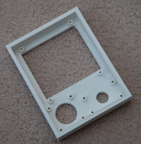
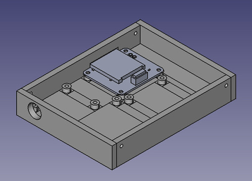
This is the base design I came up with. You can also see one of the Gadgeteer part designs where it will be fitted in the finished product.

I’ve been designing a box for the “Door of Mystery” Gadgeteer device that I built for the Red Nose Day event. But I’m very lazy. I don’t want to have to lay out the various elements by hand and position them individually. I want this to happen automatically. So I’ve wanted to write a program to do this. Peter likes OpenSCAD, so I went there first.  OpenSCAD lets you create 3D images programmatically. It is really easy to use, and you can preview your designs very quickly.

module panel(width, height, x, y)
{
    translate([x,y,0])
    {
         cube(size=[width, height, baseDepth]);
    }
}

I used this tiny snippet of OpenSCAD to place a panel on the drawing surface. I move the axis to the position of the panel and then create a box of the required size. You can perform unions to merge things together and differences to cut one shape from another. In no time at all I was programmatically creating bases for the Gadgeteer devices. And then I hit a brick wall. What I really wanted to do was have the program work out where each device goes in relation to the other ones and lay out the box contents.To do that my program has to keep track of where things have been put. This means that I need some variables.

OpenSCAD does not provide variables as such. It provides constants (such as baseDepth above) but these are evaluated at compile time, and so I can’t use them to keep track of things as the program runs. This is not necessarily a criticism of OpenSCAD, it isn’t really meant to run programs, but it does mean I can’t use it.

So I went back to my old friend FreeCAD. I first used this ages ago, when I made the case for my Tweet Printer. FreeCAD can be controlled by Python programs and I’ve always fancied learning a bit of Python, so of I went. The designer has a Python console into which you can paste and run lumps of code. You can also add libraries and user interfaces on top, but I was happy to cut and paste for now. All the actions you take in the designer are exposed as Python calls via the console, which makes it quite easy to figure out how to do things. You just do it in the designer and then look at what comes out on the console. There is also an API reference which tells you how the commands work.

def makeBoard(self,x,y):
    b = Part.makeBox(self.width,self.height, 5, Base.Vector(x,y,0))
    return b

This method is a member of my “Filler” class which places the filler (which has a width and a height) at a particular place on the design. Note that the filler is 5mm thick in the above code. The program can take the object that is returned and fuse or cut it with other shapes as you build up the finished design. By the end of all my fiddling I’ve got a class hierarchy of Gadgeteer device specifications and a layout engine that will place them in a box of a particular size.

def MakeTop():
    doc=FreeCAD.newDocument()
    f1 = Filler("Filler", 5,25)
    f2 = Filler("Filler", 6.5,25)
    f3 = Filler("Filler", 6.5,20)
    rfid = RFIDReader("rfid", "landscape")
    camera = Camera("camera", "landscape")
    display = DisplayT35("display", "portrait")    
    topComponents = [rfid,f1,camera,f2,display,f3]
    test = Layout(91,121,topComponents)
    board = test.layout()
    Part.show(board)
    Gui.SendMsgToActiveView("ViewFit")
    Gui.activeDocument().activeView().viewAxometric()

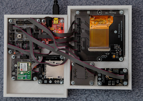
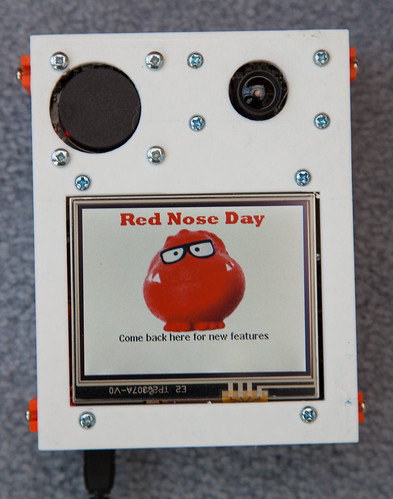
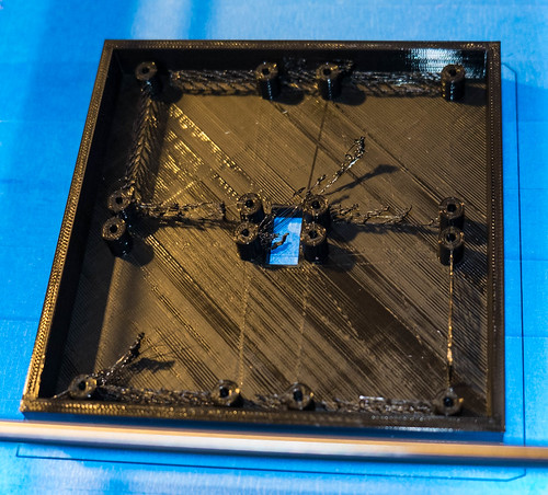
The MakeTop method creates the top of the box which contains an RFID reader, a touch display and a camera. These are laid out in an area with a dimension of 91x121 mm. Each component can be either “landscape” or “portrait” orientation and you can create filler elements to push things around in their row. The design method is given a list of components and an output area. The finished design looks like this:

TopDesign

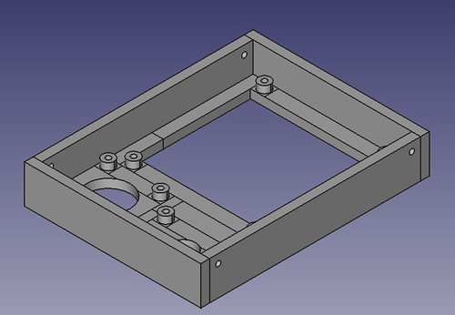
These elements cut extra holes for themselves so that they show through the front of the box. The layout method also creates the sides and puts fixing holes in them, so that I can join the top and the bottom together. If I want different size of panel thicknesses I just change the static members that control these values and run the method again. If I want to make a different design I just create a new method which contains the devices that want.

The system is not completely automatic, what I end up doing is fiddling with the output from the method and then changing the orientation and adding fillers until I get what I want. The good news though is that it provides a really quick way of making Gadgeteer boxes. I’m going to have a go at printing the designs later in the week.

I find it fascinating that I’m now writing programs where the output is a physical artefact. We do live in interesting times.

TechDays 2013 Sessions Now Online

image

If you want to see a proper Gadgeteer session, not in rhyme, but with working demos and a lot more detail, then you can get hold of my TechDays session on gadget development by clicking on the above image. If you want to see all my Channel 9 sessions (including the ones on Windows Phone Agents and Windows Phone Speech) you can find them here:

http://channel9.msdn.com/Events/Speakers/Rob-Miles

Red Nose Day Door of Mystery

DSCF0363.jpg

Sometimes a good idea can take away your entire Sunday.

“The Door of Mystery” is an unique fundraising idea that takes the old style, simple, raffle idea and turns it into a new, high-tech, complicated form. To take part all you have to do is buy one of our special “Red Nose Day” tags for two pounds and then take it to “The Door of Mystery” at my office in the Robert Blackburn building to find out your entry number. Then, at the presentation on Friday we will build a “Door of Mystery” machine of our own and then use it to pick the winner of the competition. The prize, courtesy of Microsoft Research Cambridge, is a Gadgeteer kit of your own.

The tags contain an RFID chip which is read by a Gadgeteer board inside the door unit. The unit contains an SD card with a list of RFID values which are mapped to entry numbers. Show your tag to the door and it will tell you your magic number.

DSCF0373.jpg

This is the guts of the prototype device. I’ve cannibalised my Tweet Printer case to use for the project. I’m going to print a proper one later. If I get round to it.

DSCF0383.jpg

I’ve got 100 RFID tags to sell for Comic Relief. Each one has been keyed to the system and you can buy them from the departmental office. Perhaps we’ll think of other uses for them over time..

You can sponsor the whole shebang over at: http://my.rednoseday.com/sponsor/robmiles

Catching Heartbeats with the Gadgeteer

image

I reckon the Gadgeteer has more interfaces than just about any other embedded framework. Including neat things like this Pulse Oximeter from Seeed. They make the point on the product description that you should not use this as a medical instrument but, what with the theme of GlobalGameJam being heartbeats, and me having one to play with, the temptation to use it in our game was very hard to resist.

Using it is very easy indeed. You can bind to events that fire when connected (i.e. someone has put their finger into the sensor), disconnected (when someone has pulled their finger out, so to speak) and on a pulse detected event. You can also read the sensor object to find out pulse rate, blood oxygen levels and signal strength.

This is my code to bind methods to the sensor events:

pulseOximeter.ProbeAttached += 
   new PulseOximeter.ProbeAttachedHandler(pulseOximeter_ProbeAttached);
pulseOximeter.ProbeDetached += 
   new PulseOximeter.ProbeDetachedHandler(pulseOximeter_ProbeDetached);
pulseOximeter.Heartbeat += 
    new PulseOximeter.HeartbeatHandler(pulseOximeter_Heartbeat);

The handlers then do all the work:

void pulseOximeter_Heartbeat(PulseOximeter sender, 
PulseOximeter.Reading reading) { sendMessage("P" + reading.PulseRate.ToString()); }

The sendMessage method takes a string and sends it on to the game via a serial port interface that is also connected to the Gadgeteer device. The sensor has proved to be quite sensitive and works rather well. It is quite unnerving to be playing a game and find that the gameplay matches your heartbeat.

Printing LED Enclosures with Ultimaker

DSCF0325.jpg

Spent some time today doing some 3D printing with the Ultimaker. And by some time I mean quite a while.

DSCF0338.jpg
Nearly a six hour print, one of my longest so far

I’m making an enclosure for a set of Gadgeteer LED Matrix Modules from GHI. I want to combine four of them to make a 16x16 dot LED display. Once I’ve built it and got them working I’ll figure out what to do with them. I spent a while last week printing out version one of the enclosure. Rather stupidly, I made this exactly the right size, i.e. 120mm wide internally. I figured that since the units were 60mm in size each that would work fine. Not so. It made them just the right size to not fit. It is a testament to the Ultimaker printer that they would not fit either way because they were exactly the same size as the opening in the enclosure. Darn.

So it was out with FreeCad and away to design a new enclosure with an extra mm all round, so that I could actually get the units into it. I also added some support pillars that engage with the Gadgeteer boards behind each display. What I need now are some really slim nuts so that I can bolt the displays in place.

DSCF0340.jpg

This is the finished print, complete with “sprue” that I’ll have to clean off. It took me ages to prise it off the blue tape. I think I need to adjust the platform a bit to make the top layer a bit smoother although, for this build, you don’t actually see this bit.

DSCF0344.jpg

Here is the tray with the LED units fitted.

New Embedded Stuff

There are quite a few new embedded toys that I’ve discovered just recently. Here are three.

image

First up is the DAGU racer. This is a neat little Bluetooth controlled racing car. They’ve got it on discount at RoboSavvy at the moment. It comes with an Android app that you can use to control it, but they also expose the Bluetooth command set so that you can control it from anything, including Gadgeteer I reckon. It is powered by a tiny lithium ion battery and even comes with a set of stickers you can use to customise the racer. And for under twenty quid it was very tempting. So I got one.

image

I got all excited when I first found out about the Electric Imp. This is a wireless embedded device that fits into an SD card socket. You can’t actually use it as a memory card but you can use it to control a connected net appliance. And you can get it for around twenty quid. My excitement dissipated quite a lot though when I discovered that every device is bound to the imp cloud service which is where it registers its data and where messages come from.

I’ve bought these kinds of devices before, my Chumby and Nabaztag rabbit worked in a similar way. The idea of the company behind them is usually that they don’t make much money on the devices themselves, but build a subscription model which lets them pay for the infrastructure by getting cash somehow from the users of each device. Snag is, if that doesn’t work and the company goes bust you are left with a paperweight.The folks behind the imp seem quite confident that they can make it work, and the service is free at the moment. But they are talking about $50 subscriptions for business users and stuff like that, so I think I’ll pass on this, amazing as it is.

image

Now this I really do like. It brings you the best of the .NET Micro Framework, Arduino and Gadgeteer in a single board that costs less than thirty quid. You can feed it five volts and it just works. You’ve got an Arduino shield, three Gadgeteer ports, SD card, USB client and host and a space to put an Xbee or WiFi receiver. I’ve been looking at very simple devices that I’d like to make using the Gadgeteer and wanting a cheap, simple board that just gets things done. The FEZ Cerbuino Bee seems to fit that bill perfectly. For less than the price of a video game you get a device you can program with .NET, connect lots of Gadgeteer devices to and put onto WiFi at a bearable cost.

If you are learning C# and want to dip your toes into embedded development I can’t think of a better start. Lovely.

Reading your Gas Meter with Gadgeteer

IMGP0058.jpg

One of my favourite cartoons when I was a kid was a picture of a bloke in a uniform wearing the logo of the Gas Company, with a notepad and pen in his hands and looking exhausted. Someone says to him “You look tired” and he replies “So would you be if you’d just done 100 meters”.

Funny eh? Peter doesn’t want to have to wait until his gas supplier tells him how much gas he has used, he wants to know instantly the effect of having that hot bath. You can find out how he is using Gadgeteer to read meters safely by reading this.