Making Boxes with Software
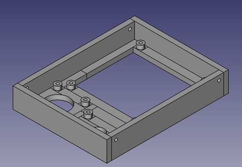
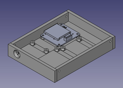
/This is the base design I came up with. You can also see one of the Gadgeteer part designs where it will be fitted in the finished product.
I’ve been designing a box for the “Door of Mystery” Gadgeteer device that I built for the Red Nose Day event. But I’m very lazy. I don’t want to have to lay out the various elements by hand and position them individually. I want this to happen automatically. So I’ve wanted to write a program to do this. Peter likes OpenSCAD, so I went there first. OpenSCAD lets you create 3D images programmatically. It is really easy to use, and you can preview your designs very quickly.
module panel(width, height, x, y)
{
    translate([x,y,0])
    {
         cube(size=[width, height, baseDepth]);
    }
}
I used this tiny snippet of OpenSCAD to place a panel on the drawing surface. I move the axis to the position of the panel and then create a box of the required size. You can perform unions to merge things together and differences to cut one shape from another. In no time at all I was programmatically creating bases for the Gadgeteer devices. And then I hit a brick wall. What I really wanted to do was have the program work out where each device goes in relation to the other ones and lay out the box contents.To do that my program has to keep track of where things have been put. This means that I need some variables.
OpenSCAD does not provide variables as such. It provides constants (such as baseDepth above) but these are evaluated at compile time, and so I can’t use them to keep track of things as the program runs. This is not necessarily a criticism of OpenSCAD, it isn’t really meant to run programs, but it does mean I can’t use it.
So I went back to my old friend FreeCAD. I first used this ages ago, when I made the case for my Tweet Printer. FreeCAD can be controlled by Python programs and I’ve always fancied learning a bit of Python, so of I went. The designer has a Python console into which you can paste and run lumps of code. You can also add libraries and user interfaces on top, but I was happy to cut and paste for now. All the actions you take in the designer are exposed as Python calls via the console, which makes it quite easy to figure out how to do things. You just do it in the designer and then look at what comes out on the console. There is also an API reference which tells you how the commands work.
def makeBoard(self,x,y):
    b = Part.makeBox(self.width,self.height, 5, Base.Vector(x,y,0))
    return b
This method is a member of my “Filler” class which places the filler (which has a width and a height) at a particular place on the design. Note that the filler is 5mm thick in the above code. The program can take the object that is returned and fuse or cut it with other shapes as you build up the finished design. By the end of all my fiddling I’ve got a class hierarchy of Gadgeteer device specifications and a layout engine that will place them in a box of a particular size.
def MakeTop():
    doc=FreeCAD.newDocument()
    f1 = Filler("Filler", 5,25)
    f2 = Filler("Filler", 6.5,25)
    f3 = Filler("Filler", 6.5,20)
    rfid = RFIDReader("rfid", "landscape")
    camera = Camera("camera", "landscape")
    display = DisplayT35("display", "portrait")
    topComponents = [rfid,f1,camera,f2,display,f3]
    test = Layout(91,121,topComponents)
    board = test.layout()
    Part.show(board)
    Gui.SendMsgToActiveView("ViewFit")
    Gui.activeDocument().activeView().viewAxometric()
The MakeTop method creates the top of the box which contains an RFID reader, a touch display and a camera. These are laid out in an area with a dimension of 91x121 mm. Each component can be either “landscape” or “portrait” orientation and you can create filler elements to push things around in their row. The design method is given a list of components and an output area. The finished design looks like this:

These elements cut extra holes for themselves so that they show through the front of the box. The layout method also creates the sides and puts fixing holes in them, so that I can join the top and the bottom together. If I want different size of panel thicknesses I just change the static members that control these values and run the method again. If I want to make a different design I just create a new method which contains the devices that want.
The system is not completely automatic, what I end up doing is fiddling with the output from the method and then changing the orientation and adding fillers until I get what I want. The good news though is that it provides a really quick way of making Gadgeteer boxes. I’m going to have a go at printing the designs later in the week.
I find it fascinating that I’m now writing programs where the output is a physical artefact. We do live in interesting times.


