Chocolate Synthbox Video
/The start of the day was just about cool enough for me to sneak into the conservatory and record a little video about the Chocolate Synthbox. I’ve also built the GitHub repository for the project. You can find it here.
The start of the day was just about cool enough for me to sneak into the conservatory and record a little video about the Chocolate Synthbox. I’ve also built the GitHub repository for the project. You can find it here.
I’m quite enjoying making silly sounds and tunes with the Chocolate Synthbox. It’s still a bit unreliable. I’m having problems getting some of the components to wake up in a correctly configured state, but when it is working it is great fun.
You’ll be able to find out all about the device and what it does in an upcoming Hackspace article.
Isn’t this exciting? I’m just on the brink of sending useful messages between my PICO powered controller (which has buttons and a display) and a Pure Data patch running on a Raspberry Pi. Last time I got the comport working now that I can send raw data bytes between the devices. Now I want to see about sending packets of useful data.
The man behind Pure Data (Miller Puckette) has thought of this. He’s invented the FUDI protocol for sending messages. It’s a very simple text based protocol which means that it will be very easy to make the PICO assemble FUDI messages for the Pure Data patch to read.
Lets take a look at the kind of message that I might want to send from the controller to a Pure Data patch:
encoder 97 5;
The controller generates messages like this when an encoder is turned. The word encoder tells the receiver that a new encoder value is coming The first number (97) is the new encoder value. The second number (5) is the number of the encoder. The encoder message is generated by Circuit Python running inside a PICO which is connected to the encoders and sends messages out over the serial port. The Python code that sends these messages is:
b1 = int(self.active_config.serial_channel)
b2 = int(self.active_config.controller_value)
message = "encoder " + str(b1) + " " + str(b2) + ";\n"
send_buffer = bytes(message,"ascii")
print("Sending to serial:", send_buffer)
self.client.serial_port.write(send_buffer)
This code takes the two values and puts them into the variables b1 and b2. Then it creates the message string. Next it makes a byte array containing the message in ASCII. Finally it uses the serial_port_write method provided by the serial port to send the entire string out to the Pure Data patch. Now lets take a look at how this serial data stream is received.
My blog post here shows how to get a Pure Data patch to receive data from a com port. At the bottom of the patch you can see a data flow coming out of the comport object and ending in a rather enigmatic way. The patch decodes the input message and routes it to the required destination. It uses a Pure Data loop to assemble the message (which is a line of text) and then uses FUDI (Fast Universal Digital Interface) to parse the text and extract a message which is then routed to the appropriate destination.
Remember that what is happening is that individual bytes are arriving, one at a time, and need to be assembled into a line of text. The text is terminated by a newline character (10) or a return (13).
The sel object at the top of the patch takes the input stream and feeds it to one of three outputs. If the input value is 10 or 13 (the characters that mark the end of the list) the list is triggered to push its contents into the fudiparse object. If the input value is anything else (this is what the right hand output from sel is for) the newly received character is added to the start of the list, building up the line of text.
The fudiparse block takes the buffer containing the incoming message (in our case “encoder 97 5” and uses it to generate a Pure Data message that contains the values “encoder”, 97 and 5. This message is then sent into a route object. This looks at the first item in the message and then sends the rest of the message (the values 97 and 5) to the output that matches that name. In the case of the patch above, this means that the two encoder value are sent to a message endpoint called “encoderReceived”. Patches in other parts of the of the application can receive these messages and act on them.
You should be able to work out that the decoder above can also respond to an incoming message called button, which tells the Pure Data application when a button was pressed.
I’m building a Raspberry Pi 4 based device that uses a thing called Pure Data to play sounds in response to incoming MIDI messages. The device also has a controller and display which is controlled by a Raspberry Pi PICO. I’ve connected the hardware for a serial connection and discovered how to send serial messages from the Circuit Python program in the PICO. Now I need to get the messages from the PICO into my music making software. This is how to do it.
The above patch fragment (is that even a thing?) shows how it we can surface serial data in a Pure Data patch. However, before we can do this we have to add the comport object to your Pure Data installation. If you re using a Raspberry Pi it turns out that this is very easy:
sudo apt install pd-comport
This console command installs the comport object. Now we can add one to our patches. The patch above shows that we can send it messages to make it do things. The message on the left sets the device name. The second messages sets the baud rate. The third message asks the comport to display all the available comports that Pure Data has found.
When the above patch is triggered by a message on the inlet it will set up a comport and set the baud rate to 19200. Any messages that we send to the comport object will be sent out of the comport. These need to just lists of bytes. If the comport receives any bytes from these are sent out of the bottom of the comport object. In a while we’ll take a look at how we can encode and decode messages that we want to send over the serial connection.
I want the Pure Data patches in my Chocolate Synthbox to be able to display lights that flash in time with the music. The lights in question are a bunch of neopixels connected to a Raspberry Pi PICO which is handing all the inputs and outputs for the device. I’ve done this to keep the design simpler and to remove any chance of issues with the sound code on the Pi interfering with the pixel animations.
However, to make it work I have to connect the Pi and the PICO together. Both devices have plenty of serial ports, so the best way is just to use one of those.
On the Raspberry Pi 4 (note that this only works for the 4) there are four serial ports which are surfaced on the “hat” connector. You have to enable them and they surface as devices you can use.
You enable them by editing the /boot/config.txt file:
sudo nano /boot/config.txt
Then, if you want to enable serial port 2 (which I do) add the following line at the end of the file:
dtoverlay=uart2
Save the file and then restart the Pi. You can now ask it which pins it uses with the command
dtoverlay -h uart2
The important part of this information is the “uart 2 on GPIOS 0-3. This means that the pins will be assigned as follows:
Pin 27 GPIO0 UART2 TX
Pin 28 GPIO1 UART2 RX
The other two pins (GPIO2 and GPIO2) can be used for hardware handshaking, but I’ve not enabled that. The device will appear as /dev/ttyAMA1, I’m going to use it in Pure Data (but that’s a different blog post. For this one, let’s discover how to connect the port to a PICO. I’ve decided to use uart1 in the PICO. This can be used on pins GP8 (TX) and GP9 (RX). So the wiring I need is:
Raspberry PI         PICO
Pin 38 GND           Pin 13 GND
Pin 27 GP0 UART TX   Pin 12 GP9 UART1 RX
Pin 28 GP1 UART RX   Pin 11 GP8 UART1 TX
Note that the TX and RX are crossed over. The PIC is running Circuit Python, this is how to connect a program to this port:
serial_port = busio.UART(board.GP8, board.GP9, baudrate=19200,receiver_buffer_size=500)
Now if the Circuit Python program in the PICO sends data to this port it can be picked up in the PI.
Today I needed to find a way to auto start a Pure Data patch when a Raspberry Pi boots up. This is so that the Chocolate Synthbox (patent pending) can play sounds without the owner having to do anything to get it going.
Above you can see how I did it. The /etc/xdg/lxsession/LXDE-pi/autostart file contains commadns that are obeyed once the desktop has loaded. I used this command to start the editor:
sudo nano /etc/xdg/lxsession/LXDE-pi/autostart
I added the line you can see at the bottom:
sudo pd /home/pi/Desktop/Synthbox/ChocSynthboxMain.pd
This works well for me because the file Synthbox on my desktop contains the file ChockSynthMain.pd If you want to use it you change this to the location of your Pure Data patch.
You can use this technique to start any other programs on power up.
I’m really looking forward to emfcamp this year. I went to the last one four years ago and it was excellent. Last time I attended lots of splendid sessions and just enjoyed the atmosphere. This time I’m presenting as well. I’m going to be showing off my Chocolate Synthbox synthesizer and describing how you could build one of your own. It’s going to be great fun. Trust me.
There are lots of other great sessions too. You can find the complete list here.
Did you know that there are two sizes of 8x8 neopixel panels? I do now, having bought a new one and discovered that it is too small to fit over the pixels in the box I’ve just printed. Wah.
And then I discovered that the box I’d just managed to print was too small to take the PICO and the connections. The lid wouldn’t fit properly. As you can see, I have managed to fix this problem though. I’ll tell you how I did it tomorrow.
Yesterday I rediscovered something that I have now learned many, many times. I’m hoping that writing it down in the blog will make it stick this time. Worst case it will turn up in a search next time I try to find out why my neopixels are flickering. It’s all about supply and signal voltages. A rule to remember is:
The voltage on the data signal for a neopixel must be at least 60% of the power supply voltage.
If your power supply is 5 volts and your data signal is 5 volts you are laughing (or at least grinning happily because it works). If your power supply is 5 volts and your data signal is 3.3 volts (which is the signal voltage used by the Raspberry Pi PICO amongst other devices) then you might not be smiling because things get a bit marginal.
Sixty percent of 5 volts is 3 volts, so in theory it should work with 0.3 volts to spare. However, if your power supply is up half a volt (which can happen) your pixels won’t light properly. Worst case your power supply voltage might vary a bit depending on load and you get pixels which work sometimes but flicker or fail to light every now and then. And it turns out that some neopixels are more fussy about the “60 percent rule” than others. So just changing to a different type of pixel can break a previously working device.
I had this problem with the pixels attached to the chocolate synthbox. I was powering the 8x8 pixel grid you can see above from the 5 volt output from the PICO device. And it flickered. Much unhappiness ensued. Devices were swapped out and reconnected to no avail. Then I remembered the 60 percent rule. And an issue reported on the PICO Chord keyboard. So, I attached the power for the pixels to the 3.3 volt output from the PICO. This solves my “60 percent problem” at the risk of raising another one, which is that the 3.3 volt output from the PICO can’t deliver much current for the lights. The good news is that if I keep the brightness levels down (which I need to anyway to stop light bleeding between the dots) it works a treat.
If you have this problem with your pixels I don’t advise that you do this every time because of the power supply issue. A better way of solving the problem is to use a level converter to lift the 3.3 signal voltage to 5 volts.
One of the great things about 3d printing is the way that you can iterate your designs very quickly. The picture above shows my progress towards a little plastic clip that will hold the led panel onto the front of the case for the “Chocolate Synthbox” that I’m building. The first one (on the far left) was a bit too large. Over the next three I refined the hole size and the height of the “claw” part of the clip until it fits and can be tightened down. Great fun.
I think I’m feeling better. I’m making things again.
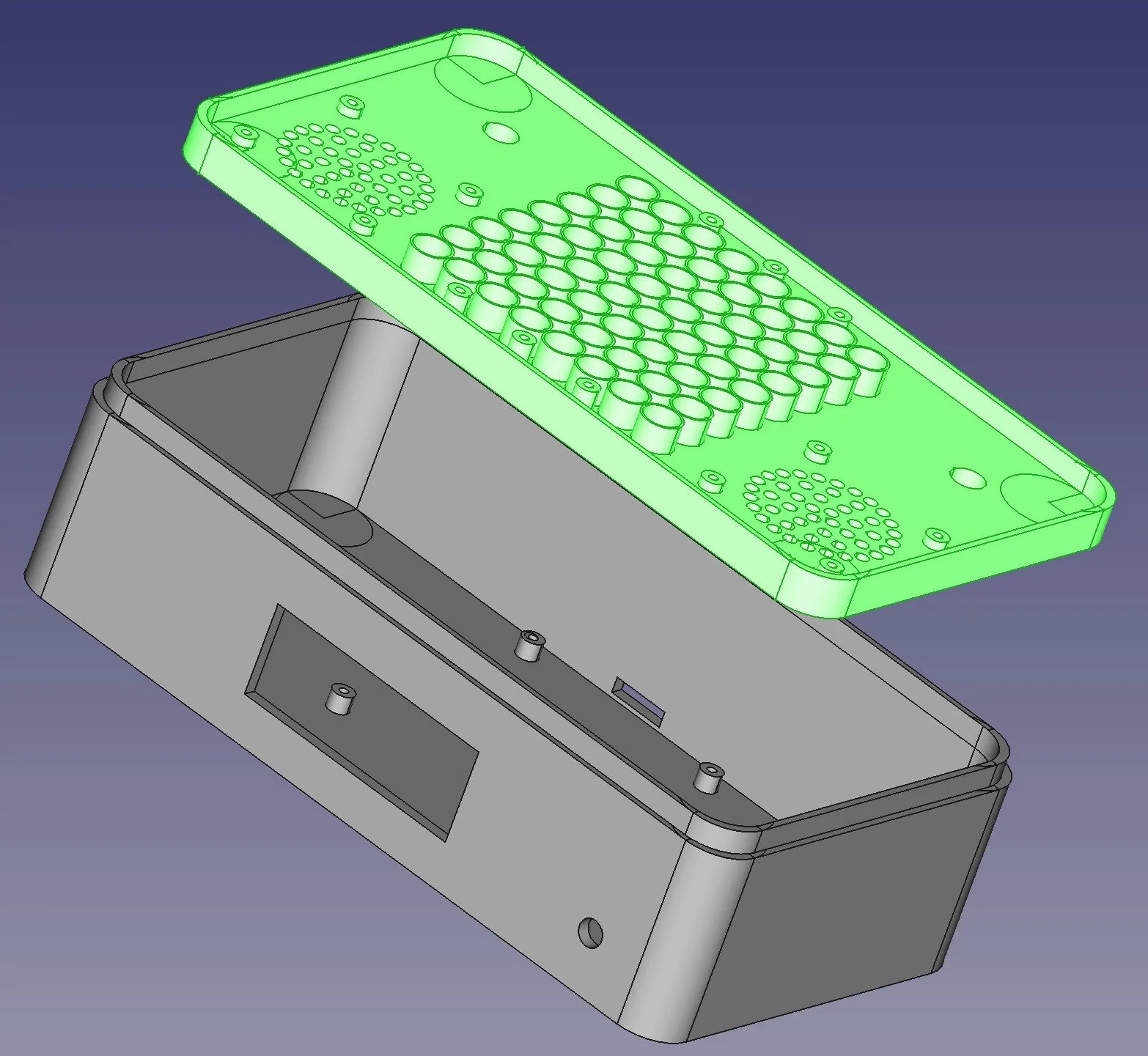
I’ve decided that I need to complete the meal that started with the MIDI Cheesebox and Crackers MIDI Controller. So I’ve started work on a Chocolate Synthbox. This going to be a Raspberry Pi powered synthesizer that you can plug the other two devices into. It’ll have built in stereo speakers, a flashy matrix display and a couple of rotary encoders. I’m going to use a Raspberry Pi PICO to do all the low level interfacing and link it to a Pure Data patch running in the Pi that will make all the sounds.
I’ve had a lovely day today designing the case you can see above. The idea is to get it right first time, as the printing times for a box this big are a bit long.
With a bit of luck I should get it working in time to reveal it to the world at emf in June.
Rob Miles is technology author and educator who spent many years as a lecturer in Computer Science at the University of Hull. He is also a Microsoft Developer Technologies MVP. He is into technology, teaching and photography. He is the author of the World Famous C# Yellow Book and almost as handsome as he thinks he is.