Making Working Microphones

I’m quite proud of the above circuit. This is not because it is especially well designed, or that it is definitely the best way to do it. I like the circuit because it does what I want. I connect the phone handset to the left hand connection and the microphone to the right and I can speak into the handset and record the resulting audio on the Raspberry Pi.

The circuit contains a “potential divider” which is a posh name for two resistors wired in series. In the above case the two resistors are R1 (the 1K resistor) and the handset carbon microphone (which measures around 500 ohms or so). One of the magical features of electricity is that a voltage “spreads itself out” across the resistors in a circuit. If the handset microphone has a resistance of 500 ohms, we put it in series with a 1K resistor and we put 5 volts across the pair of them we find that the 5 volts is spread across this circuit in a manner proportional to the resistance values. Total resistance 1,500 ohms (1K + 500). The 1K resistor is two thirds of this total, so two thirds of the voltage goes across this resistor. The point where the 1K resistor and the handset microphone are connected should therefore be at a voltage of one third of 5 volts, the other two thirds having been dropped across the 1K resistor.

If this is confusing to you consider how, back in the day, we used to make Christmas tree lights using bulbs that were powered by 12 volts. You might think that putting a 12 volt bulb across the 240 volts mains supply would cause that bulb to explode. And you’d be right. But if we connect 20 of the bulbs in series, one after another, each bulb only drops a 20th of the 240 volt supply (12 volts), so all works well. This is also horribly dangerous though. You might think that 12 volts is a safe voltage to work with, but in the case of mains powered Christmas tree lights people were regularly electrocuted. This is because a human being has a high resistance, much higher than a 12 volt light bulb. So, according to the laws of the potential divider, if I insert myself into the tree light circuit in place of a bulb, the fact that I have a much higher resistance than a bulb causes most of the 240 volts in the circuit to go into me. Ouch. Nowadays we don’t wire lights this way. A set of lights will contain a transformer which converts 240 volts into something much less tingly.

So, we have a potential divider which contains two resistors, the 1K one and the carbon microphone. Consider what happens when I speak into the microphone. The carbon granules vibrate and the resistance of the microphone changes. This changes the voltage at the point where the two resistors are connected. This change is an audio signal that represents the sound. The signal goes through a resistor (R2) to reduce its level a bit and then into a capacitor which only lets through the alternating current (the sound signal). This goes into the microphone and hay-presto, we have a sound signal.

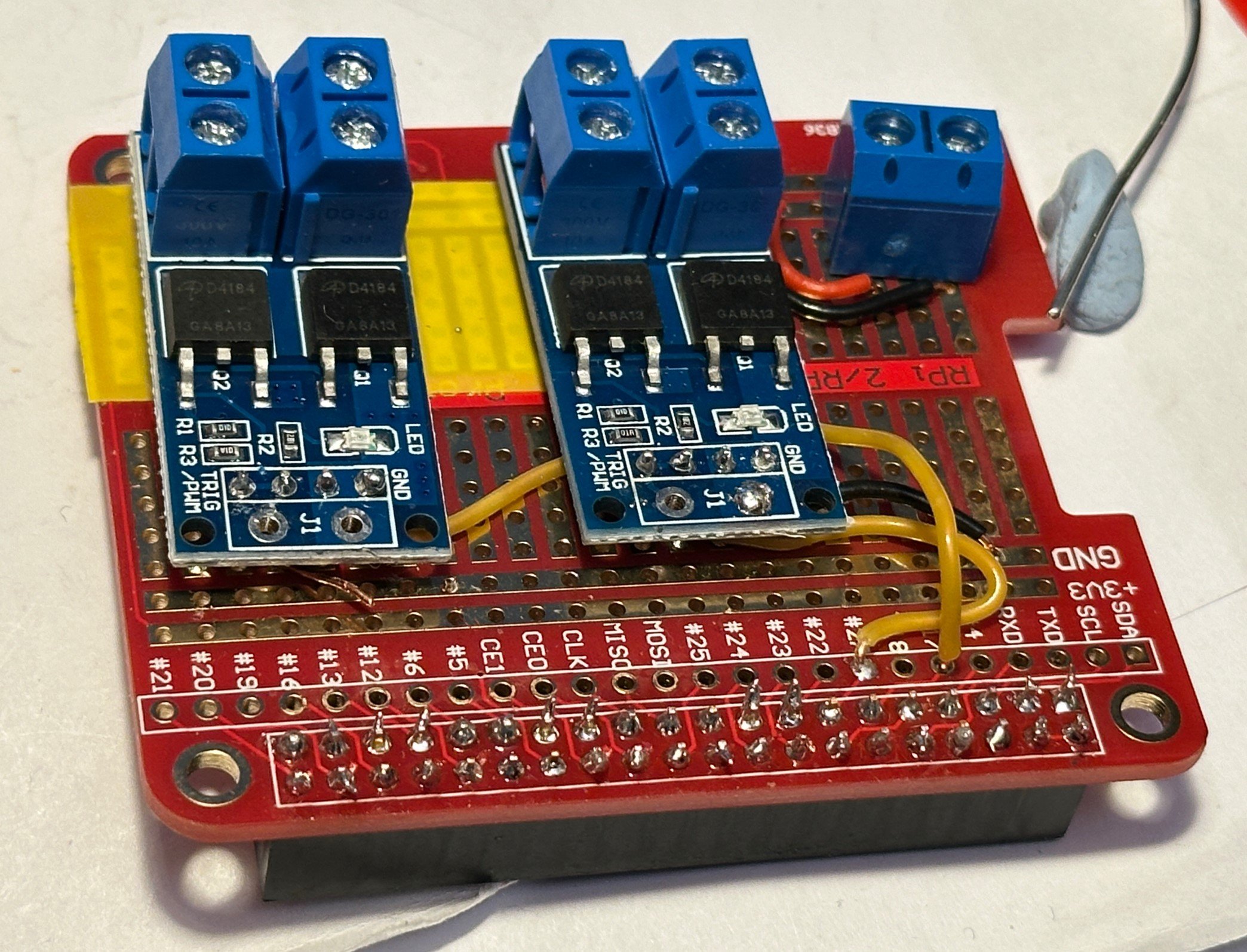
This is the third version, which is small enough to fit in the phone

Above you can see my realisation of the circuit on stripboard. I’ll spare you the sight of the soldering underneath. The circuit is now in the phone and working. Next I have to work on the software.

Making Microphones

It is a surprisingly good microphone

When I’m attacking a problem I sometimes like to have several fronts open at the same time. I’m presently trying to get speech input into my Red Telephone. The phone has a carbon granule microphone which changes in resistance in response to sound. This won’t work with the microphone input in the phone. I could either build a circuit to make the carbon microphone work with a “normal” microphone input or I could find a different microphone to put in the phone. I decided to do both. Starting with microphone replacement.

I got the microphone above with a stereo system from way back. It helps the amplifier adjust itself to the acoustics of the room its working in. The stereo is long gone, but I kept the microphone because well, you never know when you might need one. It works fine with the USB audio input I’m using with the Pi and it even fits inside the handset of the phone. But there is a problem. The handset is connected to the phone using a lovely red curly cable. This cable is not screened at all because old phone cables don’t need screening. Unfortunately, microphone cables do. So although I got an audio signal from the microphone I also got an awful lot of hum caused by the cable picking up mains radiation from the devices in the house. Oh well, on to tomorrow.

Running a Large Language Model on a Raspberry Pi 5

I never said it was perfect

I found this article which describes how you can get a something a bit like ChatGPT running on a Raspberry Pi. You need the latest Raspberry Pi 5, and it also needs the largest one with 8Gb of memory but it does work. It’s a bit slow and not very accurate, but it is fun to chat with. I think it is very useful to show slightly broken versions of the technology to folks so that they start to understand their limitations.

I’m now very tempted to make an “exchange” for the Red Phone which runs this engine and rings you back with answers to questions.

Redphone for Halloween

Only a bit scary

The “RedPhone” lives. The bell sounds like a real phone. But the insides are now possessed by a Raspberry Pi running JavaScript…..

This runs on the local network

It hosts a web page into which you can type messages and send them to the phone. When you send the message the phone rings and if you pick up the receiver you hear a ghostly voice dictate the message to you. If you pick up the receiver to make a call you get the dial tone. If you dial “2” and replace the receiver the phone will ring a few seconds later and deliver a ghostly message of doom:

randomMessages = [
    "I know what you did last summer",
    "Is that you, Boris?",
    "Look out of the window.",
    "They are on to you.",
    "Look behind you."
    ];

Other messages may be available later….

It’s been great fun to build. You’ll be able to find out all about it an upcoming article in HackSpace magazine.

Speed up Visual Studio Code Remote Development

These are the two you need to disable.

I’m writing all the code for the red telephone project in JavaScript as a node application. This is because it makes it very easy to host a website on the phone. Also I need a lot of multi-threading and events stuff and JavaScript’s await and async stuff makes this so easy to write. Also, I like writing JavaScript.

I’m writing the code on the Raspberry Pi W that is powering the phone. This is a really useful thing to be able to do. I can set breakpoints which are triggered when hardware events occur. Then I can step through the code. I’m using Visual Studio Code, but the environment is running on my PC and I’m using the amazing Remote Development feature to develop on the Pi. But it is not without its problems. When I started doing this, things would work fine for a while and then suddenly the Raspberry Pi would lock up and progress would grind to a halt.

I did some searching and thanks to this wonderful post I discovered how to fix it. It turns out that some of the language plugins for Visual Studio Code consume humungous amounts of computer power. And when they wake up on the Raspberry Pi it is pretty much game over for development on the machine. If you search the extensions for “@builtin type” and then disable the two shown above you’ll find that things work swimmingly. You miss out on a few useful goodies, and you’ll have to re-enable these to get them back, but in the meantime at least you’ll be able to do useful work on a device costing less than a couple of burgers and fries.

Soldering Idiocy

The only person I allow myself to get really cross with is me. Today I had a perfect opportunity. I’d just received the rather nice MOSFET power switches you can see above. They are rather nice because you can connect them directly to a 3.3 volt signal and they will switch a high power load (in this case 35 volts going to a telephone bell). So I soldered a pair to a prototyping board. They’re the funky blue things with the terminal blocks.

We’ll leave aside the quality of the soldering on the connector terminals at the front of the board. I was finding it hard to make any kind of soldering work when I did those. I really did think I was losing my touch. But it turned out that it was because the solder bit had broken inside the soldering iron and the temperature had got set way too low.

The reason I got really annoyed was because the MOSFET board on the left hand side has been soldered into the wrong column. It should be one position to the left. This means that all the wires (several of which are underneath the board) are in the wrong place. Idiot. And especially idiot because I thought to myself “Careful not to solder this in the wrong place” as I actually soldered it into the wrong place.

Oh well, I’ve got spares.

Ringing a bell is surprisingly complicated

def ding(self):
        # start the clapper moving towards bell 1
        GPIO.output(self.bell1GPIO, GPIO.HIGH)
        time.sleep(0.016)
        # stop the clapper moving
        GPIO.output(self.bell1GPIO, GPIO.LOW)
        # pull the clapper back from bell 1
        GPIO.output(self.bell2GPIO, GPIO.HIGH)
        time.sleep(0.01)
        # leave the clapper in the middle
        GPIO.output(self.bell2GPIO, GPIO.LOW)
        # let the bell ring for a while
        time.sleep(0.01)
        # start the clapper moving towards bell 2
        GPIO.output(self.bell2GPIO, GPIO.HIGH)
        time.sleep(0.016)
        # stop the clapper moving towards bell 2
        GPIO.output(self.bell2GPIO, GPIO.LOW)

After a bit of experimentation I’ve managed to make the bell in the old telephone sound realistic. The original bell was just fed with 70 volts AC alternating at 18 cycles a second. The code above triggers the two coils in the bell to allow it to make do with 35 volts. It was quite fun to write. I hope the neighbours don’t mind the way that I seem to be getting a lot of phone calls…….

My diodes arrived...

I’ve been making a circuit that lets a Raspberry PI PICO ring an old style telephone bell. Yesterday I discovered that voltage pulses generated in the coils that power the bell were destroying the MOSFETS that I was using to control the power. Today I got some diodes that I was able to fit across the coil connections. Now the bells ring out loud and clear. It’s so loud you can hear it next door. Which might not be a good thing.

Exploding MOSFETS

I didn’t see any sparks though..

My MOSFETS arrived today. I connected them into a circuit that controls the power to a telephone bell using a Raspberry Pi PICO. They worked quite well. For a while. Then the ringing stopped. I was pretty sure what the problem was. It’s all to do with collapsing magnetic fields. The bell is operated by a coil which turns magnetic when you put power through it. This attracts the “donger” (for want of a better name) which strikes the bell making it ring. Then, the coil is turned off and another one turned on to move the “donger” in the opposite direction towards the other bell. If you do this around 20 times a second you get the ringing sound you get in old films and TV shows.

The snag is that when you turn off a circuit containing a coil the magnetic field the coil has generated collapses, and when it does this it induces a voltage in the coil. This behaviour is used to good effect in transformers and car ignition systems but in this case we end up with a bunch of voltage with nowhere particular to go except back up the wire into the MOSFET that just turned it off. Sometimes you get lucky and he pulse causes no damage. Other times you don’t. I’ve been kind of lucky. Only one of my MOSFETS is broken. The good news is that I know exactly what to do. I need to put a diode across the coils to short out any induced voltages and stop them causing damage.

They really knew how to make things back in the sixties

Started a new project today. I’m taking an old phone and making it more interesting. It’s going to have a Raspberry Pi inside along with extra circuitry to make the bell ring. Which is proving interesting. The bell in old phones is triggered by a 70 volt ac signal. Now, 70 volts is the far side of “tingly”. Anything below 50 volts is probably OK to grab hold of, but 70 could give you a shock you could do without. Especially at my age.

I’ve manged to get an inverter to convert 12 volts into a slightly less nerve jangling 35 volts or so. The plan is to drive the two coils that work the bell (you can just see them at the very top of the picture above) separately. So that I only use half the voltage. All I need is another MOSFET power driver (I’ve said this many times) so that I can control each coil individually. It should arrive tomorrow. I’ll add it to the circuit that I’ve already built which uses one MOSFET so that I can make the bell both “ding” and “dong”.